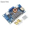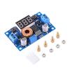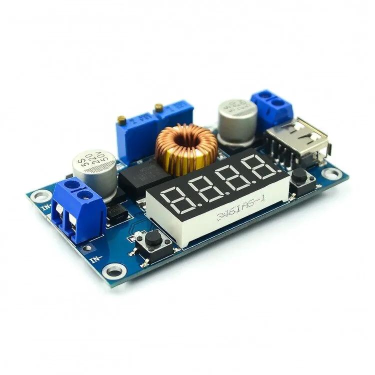

DC-DC 5A Digital LED Drive Lithum Battery Charger Module CC/CV USB Step Down Buck Converter With Voltmeter Ammeter
Түс
Суреттегідей


Сипаттамалар
Сипаттама
Dissipation Power : 1 Supply Voltage : 1 Type : Logic ICs Origin : China Condition : New Origin : China Condition : New Type : Voltage Regulator
Application : Computer
modname=ckeditor 1.When you use the product, the module inputs and outputs to be isolated from ground.2.USB output voltage is consistent with the module, not a fixed 5V output. When charging for digital equipment, make sure USB output voltage is 5V. 3.Some customers report:The module can not adjust the output voltage is always equal to the input voltage.When you encounter this problem, please counterclockwise rotation of thevoltage potentiometer10 laps or more, then use the module you can adjust the output voltage. Because the factory default output voltage of about 20V. Specifications1.Input voltage range:5-36VDC 2.Output voltage range:1.25-32VDC adjustable 3.Output current: 0-5A 4.Output power: 75W 5.High efficiency up to 96% 6.Built in thermal shutdown function 7.Built in current limit function 8.Built in output short protection function 9.Input reverse polarity protection: None (if required, high current diode in series with the input). 10.L x W x H =68.2×38.8×15mm 11.Weight: 39g Application1.Use as a step-down modules with overcurrent protection Usage: (1) Adjust the right button so thatOUTLED lighted, Digital meter shows the value of output voltage ,adjust thevoltage potentiometerso that the output voltage reaches the value you want. (2) Adjust the right button so that Digital meter shows the value of output current;Wire shorted output terminal, then adjust thecurrent potentiometerso that the output current reaches a predetermined overcurrent protection value. (For example, the Digital meter displays the current value of 4A, then you can use the module to a maximum current of 4A) (3) Connected to the load. 2.Use as a battery charger Usage: (1) Make sure you need to charge the battery float voltage and charging current; (if lithium parameters 3.7V/2200mAh, then the float voltage is 4.2V, the maximum charging current 1C, ie 2200mA) (2)Under no-load conditions, adjust theVoltage potentiometerso that the output voltage reaches the float voltage; (if to 3.7V rechargeable lithium battery, the output voltage can be adjusted to 4.2V) (3)Adjust the right button so that Digital meter shows the value of output current;Wire shorted output terminal, then adjust thecurrent potentiometerso that the output current reaches a predetermined Charging current value. (4)Charge turn lamp current factory default is 0.1 times the charging current; (Battery during charging current is gradually reduced, if the charge current setting is 1A, then when the charge current is less than 0.1A, blue lights turned off, the green light is on, which means that the battery is fullycharged) (5)connected to the battery charge. (1,2,3,4 steps as: Output is unloaded, do not connect the battery) 3.Use as a LED constant current driver module Usage: (1)Adjust thevoltage potentiometerso that the output voltage reaches the value you want. (2)Adjust the right button so that Digital meter shows the value of output current;Wire shorted output terminal, then adjust thecurrent potentiometerso that the output current reaches a predetermined LED operating current. (3)Connect LED, work. (1,2 steps as: Output is unloaded, do not connect LED) Voltmeter and ammeter calibration method:Module with manual calibration function can correct display precision voltage and current, if you think the current voltage and current accuracy to meet the requirements, do not perform the following operations. (1) Output voltage calibration steps Step 1, adjust the right button so thatOUTLED lighted, Digital meter shows the value of output voltage; Press the right button for more than 2 seconds, release, Digital meter andOUTLED flashes in synchronization so that you enter the output voltage calibration mode. Step 2, press the right button (normal speed), the voltage value is adding up a unit; Press the left button, minus a unit; Due to a unit is less than 0.1V, the minimum voltage display to 0.1V, so you need to continuously press 1-5 times to see the voltmeter change 0.1V, how many times voltmeter change 0.1V by pressing the key, depending on the current display voltage, the higher the voltage, the fewer the number of press. Step 3, press the right button for more than 2 seconds, release, to exit the output voltage calibration mode. All parameters set to automatically power down to save. (2) Input voltage calibration steps Step 1, adjust the right button so thatINLED lighted, Digital meter shows the value of input voltage; press the right button for more than 2 seconds, release, Digital meter andINLED flashes in synchronization so that you enter the input voltage calibration mode. Steps 2 and 3, consistent with the output voltage calibration method. (3)Output current calibration steps Step 1, adjust the right button so that Digital meter shows the value of output Current. Press the right button for more than 2 seconds, release, Digital meter flashes in synchronization so that you enter the output current calibration mode. Step 2,Connected to the load, ammeter in series, adjust the right and left button to change the display of digital meter, so that is consistent with the ammeter display .
The line layout is compact and regular, with good electrical insulation and mechanical stability, and can maintain stable performance under different temperature and humidity environments to ensure accuracy and reliability.
In circuit design, carefully planned lines are like precision transportation networks, and lines of different widths and spacings undertake different currents and signals transmission tasks respectively. The key signal lines are impedance matching processing, which greatly reduces signal reflection and attenuation and ensures the stable transmission of high-frequency signals.
All kinds of electronic components are soldered on the circuit board, and the solder joints are full, round, and firm and reliable. Core components like chips are perfectly connected to the circuit board through fine packaging processes to achieve high-speed data processing and interaction.
This circuit board has a wide range of responses in many fields. Whether in the industrial control field that requires extremely high stability or consumer electronics field that pursues extreme performance, it can provide solid guarantees for the stable operation of the equipment with its excellent design and reliable performance, and help various electronic devices play a powerful role.